WCD Series: Center Lined Butterfly Valves
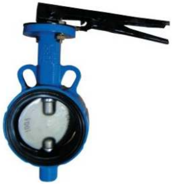
WCDSeries
Center Lined Butterfly Valves(WAFERType)
- APPLICATION: General use :water, sea water, air, hydrocarbons, acids etc.,
- SIZE: DN40 to DN4000 ( 1.5 inch to 160 inch )
- RATING: ANSI 150LB, PN10116,JIS5K110Kl16Ketc.
- CONNECTION FLANGE: See next 7 page
- WORKING PRESSURE: Up to 16 bar
- MATERIAL: See next 8 page
- OPERATOR: lever,geaI,pneumatic,HYD actuator,electric motor ect.
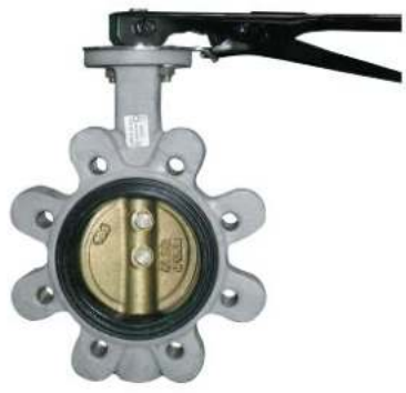
WLCDSeries
Center Lined Butterfly Valves(LUG Type)
- APPLICATION: General use :water, sea water, air, hydrocarbons, acids etc.,
- SIZE: DN40 to DN4000 ( 1.5 inch to 160 inch )
- RATING: ANSI 150LB, PN10/16, JIS5K110Kl16Ketc.
- CONNECTION FLANGE: See next 7 page
- WORKING PRESSURE: Up to 16 bar
- MATERIAL: See next 8 page
- OPERATOR: Lever,gear,pneumatic,HYD actuator,electric motor ect.

FECDSeries
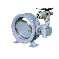
Center Lined Butterfly Valves(FLANGE Type)
- APPLICATION: General use :water, sea water, air, hydrocarbons, acids etc.,
- SIZE: DN40 to DN4000 ( 1.5 inch to 160 inch )
- RATING: ANSI 150LB, PN10/16, JIS5K110Kl16K etc.
- CONNECTION FLANGE: See next 7 pag
- WORKING PRESSURE: Up to 16 bar
- MATERIAL: See next 8 page
- OPERATOR: Lever,gear,pneumatic,HYD actuator,electric motor ect.

Hydraulic Operator
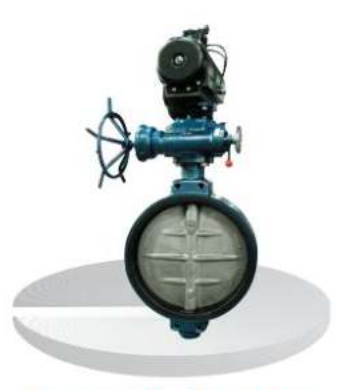
Pneumatic Operator
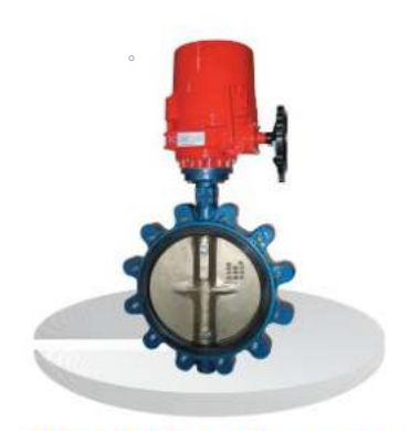
Electric Motor Operator
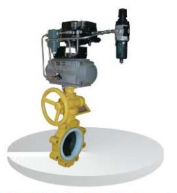
Control valve(Teflon seat)
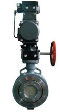
WOOl Series; High-Performance Butterfly Valve

WODTSeries
High·performanc Teflon seat Butterfly Valves(WAFERType)
- APPLICATION: General use: Chemical, petrochemicals, steam, powders etc.
- SIZE: DNSOto DN2000 ( 2 inch to 80 inch)
- RATING: ANSI1SOLB/300l600/900,PN10116/25/40,JIS10Kl16K120Ketc.
- CONNECTION FLANGE: See next 15 page
- WORKING PRESSURE: Up to 150 bar
- MATERIAL: See next 16 page
- OPERATOR: Lever,geaI,pneumatic,HYD actuator,electric motor ect.
WLODTSeries
High·performanc Teflon seat Butterfly Valves(LUG Type)
- APPLICATION: General use: Chemical, petrochemicals, steam, powders etc.
- SIZE: DN50 to DN2000 ( 2 inch to 80 inch)
- RATING: ANSI150LB/300/600/900,PN10/16/25J40,JIS10Kl16K120K etc.
- CONNECTION FLANGE: See next 15 page
- WORKING PRESSURE: Up to 150 bar
- MATERIAL: See next 16 page
- OPERATOR: Lever,geaI,pneumatic,HYD actuator,electric motor ect.

FEODTSeries
High·performanc Teflon seat Butterfly Valves(FLANGE Type)
- APPLICATION: General use: Chemical, petrochemicals, steam, powders etc.
- SIZE: DNSOto DN2000 ( 2 inch to 80 inch )
- RATING: ANSI 1SOLB/30016001900,PN10I16/25/40,JIS 1OKl16K120Ketc
- CONNECTION FLANGE: See next 15 page
- WORKING PRESSURE: Up to 150 bar
- MATERIAL: See next 16 page
- OPERATOR: Lever,gear,pneumatic,HYD actuator,electric motor ect.
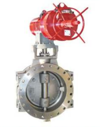
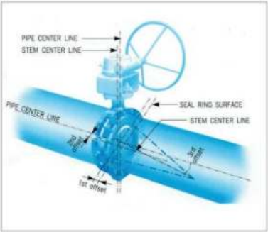
WLTOM Series; Triple Offset Metal Seat Butterfly Valve

WLTOMSeries; Triple Offset Metal Seat Butterfly Valve
- Zero leakage
- Inherently Firesafe
- Zero seaUseal friction
- Extended service life
- Bi-Direclional bubble tight shut-off by design
- Continued sealing through thermal cyding
- Excellent flow and throttling characteristics .
- Excellent control of fugitive emissions.
- Quarter tum operation
- Metal Seated
- Low operating torques.
- Torque sealed
WOOTSeries; Offset Type HP Butterfly Valve (For Steam)
-
APPLICATION
General use: Steam, Chemical, petrochemicals etc
-
SIZE
DN50 to DN600 ( 2 inch to 24 inch)
-
RATING
ANSI150LB,JIS10KJ16KJ20Ketc.
-
CONNECTIONFLANGE
See next 31 page
-
WORKING PRESSURE
Up to 25 bar
-
MATERIAL
See next 32 page
-
OPERATOR
Lever.gear,pneumatic,electric motor ect.
WW Series; Water Works Butterfly Valve

-
APPLICATION:
- General fluids: portable water, sea water
-
TYPE
- WWW Series: Short & long pattern. Flange connection.
-
CONSTRUCTIONMATERIAlS
- Body and Disc: cast iron, ductile iron, cast steel, stainless steel, steel.
- Seat: EPDM, NBR, FPM(type Viton )
- Stem: stainless steel, Monel.
-
COATING
- epoxy painting inside rubber lining
-
PRODUCTRANGE
- Sise : ON 80 to 4000 (3inch - 160inch)
-
TESTING
- According to A'NV'-JAC 504
-
CONNECTIONS
- ISO, JIS. ANSI, A'NV'-JAD, IN, etc
- Other standard upon request.
-
HANDLING POSSIBILITIES
- Gear box with indicator.
- Single or double acting pneumatic actuator.
- Electrical actuator.
Center Lined Butterfly Valve
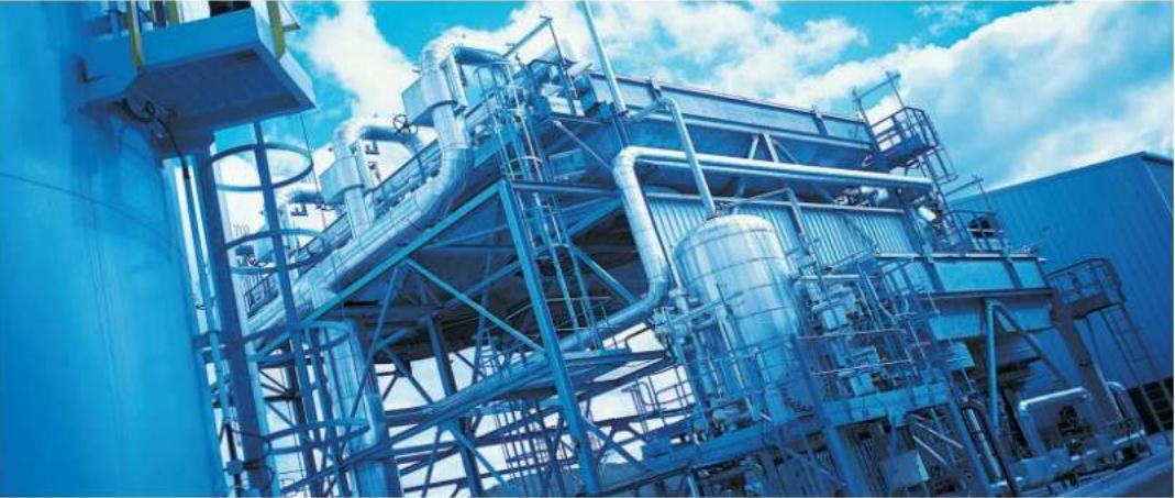


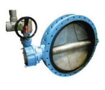
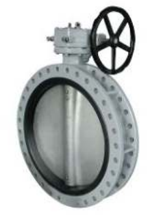
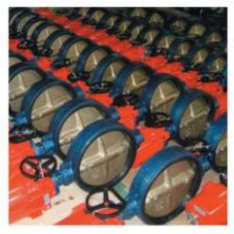
Figure Number Abbreviation
- WCD Series Center Lined Butterfly Valves - WAFER Type
- WCDSL Series Center Lined Butterfly Valves - SEMI-LUG Type
- WLCD Series Center Lined Butterfly Valves - LUG Type WLCD
- FECD Series Center Lined Butterfly Valves - FLANGE Type
Standard Compliance
Valve Center Lined Butterfly valves conform to ISO 5752, MSS SP67, JIS B 2032, JIS B 2064, API 609, BS5155, in general.
Production Range
- SIZE: ON 50 to ON 4000 (2 inch - 160 inch)
- Working Pressure: Up to 16bar
- Working Temperature: -20'U - +160'U
Connection Flange
- ANSI B16.1 CL 125LB & B16.5 CL. 150LB I MSS SP44 CL. 150LB I
- AS2129 Table 0 & E I BS4504 PN6, PN10 & PN161
- BS10 Table 0 & E I OlN2501 PN6, PN10 & PN161
- ISO 2531 PN6, PN10 & PN161 KS/JIS 5K, 10K & 16K I
- SABS 1123 Table 1000/3 & Table 1600/3
Face to face Dimensions
Conform to BS5155, ISO 5752, MSS SP67, JIS B2032, and AP1609.
Application
- Air conditioning
- Air line
- Water worlcs
- Ballast and bilge system
- ChemIcal processing
- Power plants
- Desulination plants
- Desulphunsation plants
- Shipbuilding indusUy
- Drilling rigs
- Dry powder
- Food and beverage
- Gas plant
- Healing line
- Mining industry
- Paper industty
- Sand handling
- Sugar industry
- Thenno technical water
- treatmen
- Waste water
- Water and others
Center Lined Butterfly Valve
Design Features
General Features
- 100% bi-directional tight shut off.
- Installation without restriction in direction of flow.
- Reduced weight and overall dimensions.
- Low pressure loss and reduced energy costs.
- High Kv/Cv values.
- Easy to clean and disinfect for portable water systems etc.
- Self cleaning(No residue will be trapped).
- Good resistance to corrosion.
- High reliability
No gasket required
O-rings or gaskets are not required when installation.
Low torque
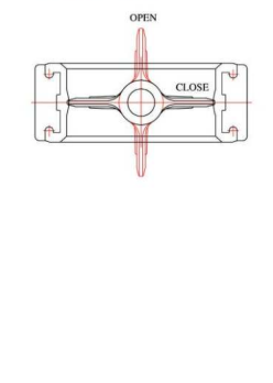
Valve discs are spherical machined and polished. Every parts of sealing surface is spherical. These fit together with a smooth and low torque when close and open. The raised center seat has the cosine-curve structure.
Perfect Sealing
Seat and disc is sealed as flat surface matched both top and bottom shaft poinl This unique sealing gives perfect tight at low torque and smooth touch. And gasket with 3 molded O-rings gives self-adjusting and positive sealing in both directions.
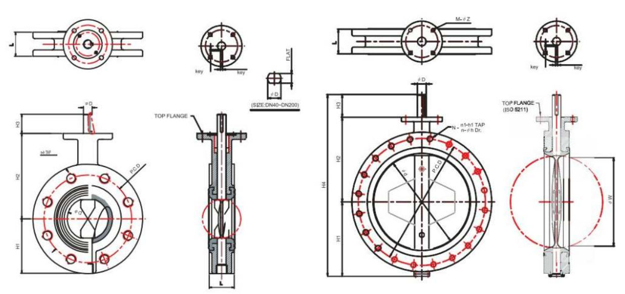
Top Flange
Top Range dimensions are in accordance with IS05211 and it matches with any type of actuators.
Testing
Valve butterfly valves are confirm to API 598 and BS5155. Body pressure test to be done 150% and shell to be 110% of maximum working pressure.
Operations
The following operation of the valves are possible, the choice is depending upon the valve location and the type of work and service for which the valve is used.
- Bare stem type valve only
- valve with 10position lever operated
- valve with gear operated
- valve with electric actuator
- valve with pneumatic actuator
- valve with hydraulic actuator
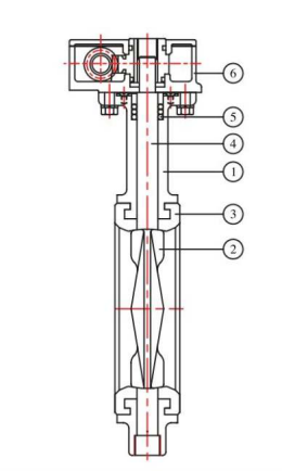
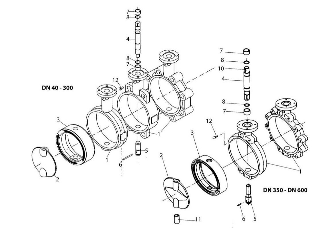
| P.NO | PART NAME | MATERIAL |
|---|---|---|
| 1 | BODY | CAST IRON 1DUCTILE IRON CARBON 5TEELI 553041 55316 AlUMINUM 1AlUMINUM BRONZE |
| 2 | DI5C | DUCTILE IRON(+NICKEL PLATED) CARBON 5TEEL(+NICKEL PLATED) 55304/553161 AlUMINUM BRONZE |
| 3 | SEAT | RUBBER (NBR 1SILICON 1EPDM 1 VITON 1NEOPRENE) |
| 4 | STEM | STAINLESS STEEL (554101 55304 1 55316/556301 MONEL) |
| 5 | PACKING | NBR,RUBBER |
| 6 | ACTUATOR | LEVER1GEAR, MOTORPNEUMATIC ETC |
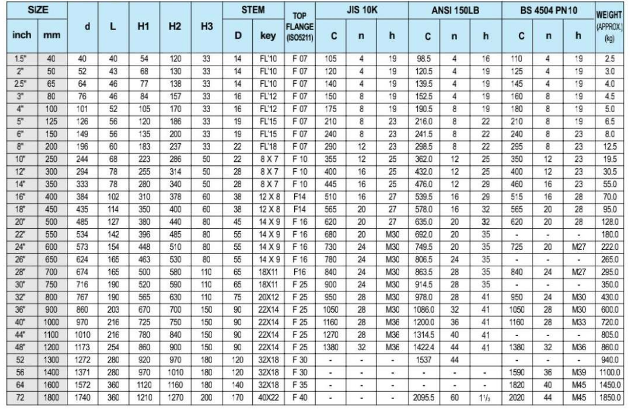
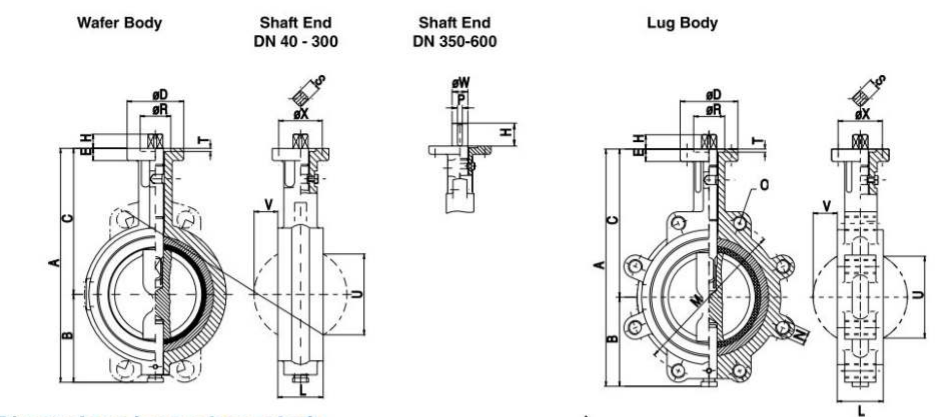
WCD Series Center Lined Butterfly Valve I Wafer Type Dimension

VALVE DIMENSIONS
WLCD Series Center Lined Butterfly Valve / Lug Type Dimension
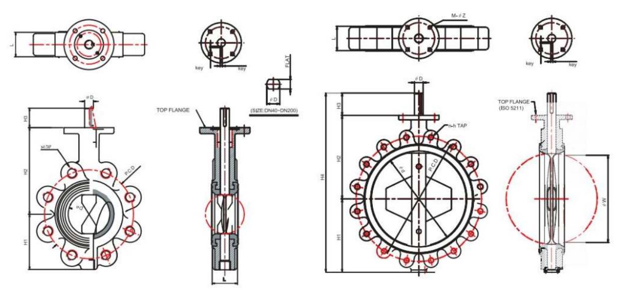
VALVE DIMENSIONS
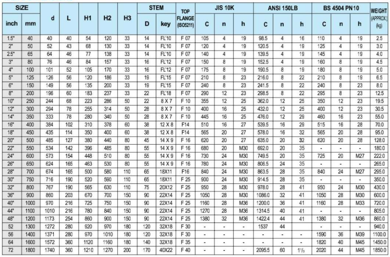
Specification and design are subject to change without notice.
WFECDSeries Center lined Butterfly Valve / Flange Type Dimension
VALVE DIMENSIONS

Specification and design are subject to change without notice.
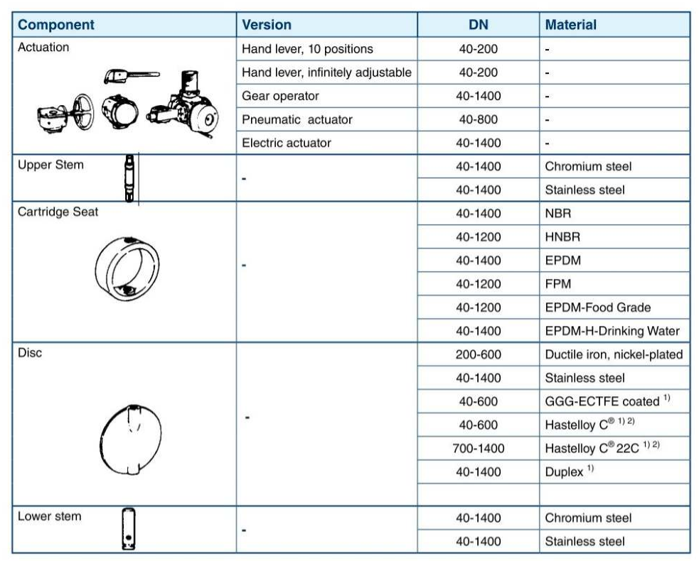
Possible Combinations
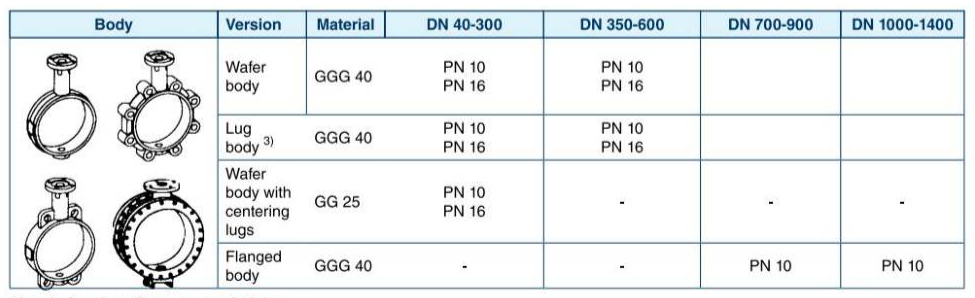
- only for shutoff pressu re of 10 bar.
- or equivalent.
- through hole thread
Material Selection - DN 40-600
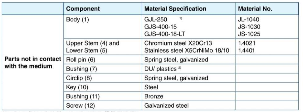
- only wafer body with centering lugs (ON 50-300).
- accordingto the manufacturer'schoice.
Material Selection - DN 40-600
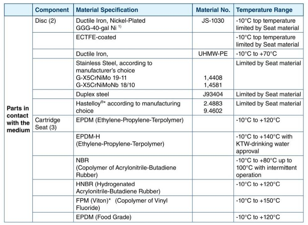
or equivalent.
- only DN 200-600.
Perbunan®I. 8 registeredtrademarkof Bayer Corporation.
Dimension and Weights DN 40-600
Dimensions in mm bare shaft
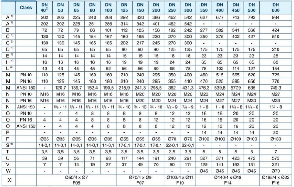
- Body made of Ductile Iron.
- Body made 01cast Iron.
- Inner parts ON 50.
- Dimensions in accordance with DtNIISO.
Weights in kg
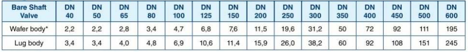
-Version with centering lugs made of cast Iron up to DN 300.
Torques Required to Operate Center Lined Butterfly Valves
TORQUE TABLE
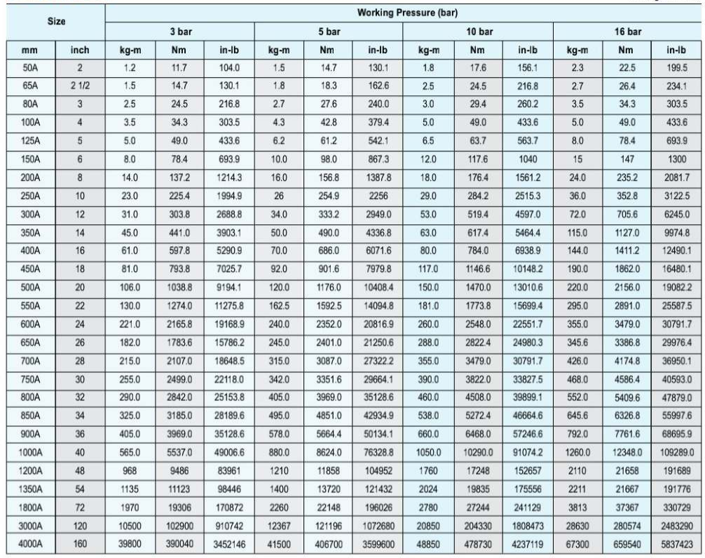
- The operating speed of the actuator must be considered in order to avoid water hammer when the valve is closed in junction with Liquid .
-
The factors affect the torque required to operate Butterfly valves
- Valve Diameler
- Shaft Diameter
- Bearing Friction Coefficient
- Type of Seat Material
- Shut off Pressure
- Velocity
- Shape of Disc
- System Head Characteristics
- Piping Arrangement
-
Actuator torques can be calculated using the following fonnulas.
Ta = Tb + Ts + Th = 1.2Tb + Td
Ts = CsD2
Tb = 4.17D1dfP
Td = ClDJP
Th = 3.06D4
V = Cf P = Q/0.785D2
Ta: The required acruator torqueflb-ft)
Ts: Sealing or unseating torqucflb-It)
Td : Dynamic torqueflb-ft)
Th : Hydrostatic torquetlb-ft)
Q : flow(cubic for per second)
V : Velocirytfeer per second)
D : Diameter of valve(feel)
d : Diameter of Shafuinch)
P : Pressure drop across valve(psi)
Cs : Coefficient of Seating or unseating torque
Ct : Coefficient of dynamic torque
Cf : Coefficient of flow
f : Bearing friction coefficient
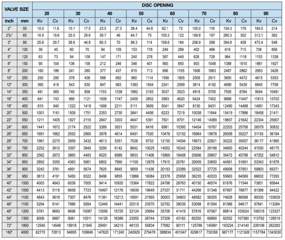
CL Series; Basic Formulas for obtaining Cv-Value
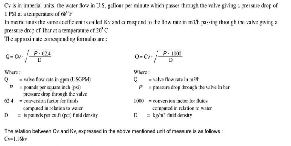
Flow coefficient for Center Lined Butterfly Valves
Installation Instructions
Storage of Valves
Store the valve in dry, dark and cool conditions, preferably indoors with the actual valve temperature higher than the dew point. If outdoor storage in unavoidable. support the valves off the ground and protect the valves with a watertight cover. Do not remove the valve packaging or end port protection, until necessary for inspection or installation. Store the valve in the slightly open position to avoid deformation of the rubberlining,
Installation Instructions
General
Before shipment, Ute seat surface is lubricated with silicone grease. Ifit is considered not necessary for special usage. it can be removed with solvent. ln case valves are for chlorine, oxygen hydrogen. valves should be cleaned and degreased perfectly Valves can be installed in Ute pipeline in any position. Before installation of valves. the pipeline must be cleaned from dirt and welding residues. Otherwise seat may be damaged. Pipes must be free of tension. Wafer and lug type butterfly valves can be installed directly in between flanges without any gaskets.
Installation in line related to wafer butterfly valve (on the existing pipeline)
Verify Ute distance between two flanges to be equal to face to face valve dimension. In order to facilitate installation of the valve, allow a sufficient room with adequate tools in between two flanges. Insert the lower part of flanges at least two flange-bolts. Close valve disc partially so that disc edge is at least 1Omm within the body. Insert valve in between two flanges. Valve will be held by the two flange-bolts previously fitted inthe lower part of flanges. Insert the flange-bolts through centering lugs of valve. Insert the remaining flange-bolts aligning the valve with the flanges and tightening flange-bolts manually. Maintain the valve aligned, remove gradually flange spreaders and tighten bolts partially. Control open and close operation of valve (0 be easy and smooth. Open the valve completely and cross tighten Ute bolts to adequate torque.
Installation of lug type butterfly valves has the same procedure with wafer type except using cap screws instead of bolts and nuts.
Installation in line related to wafer butterfly valve (on the new pipeline
Shut partially valve disc until disc profile is at least lOmm within Ute body. Align the two Ranges with the valve body. Span the body with some Range-bolts and tighten the bolts partially. Finish tightening by uniform cross bolting. Use Ute Range-valve-Range unit for pipe centering. Tack-weld the Ranges to the pipe. Remove the bolting and the valve from the flanges. Just perform tack-welding only when the valve is inserted, as high heat temperature can damage valve seat. Weld flanges to the pipe and wait until completely cooled down. Install the valve by applying the same instruction procedure as the installation instruction on the existing pipeline.
Engineering Date
Recommended Standard and Specifications
Butterfly valve manufactured according to most severe quality control standards
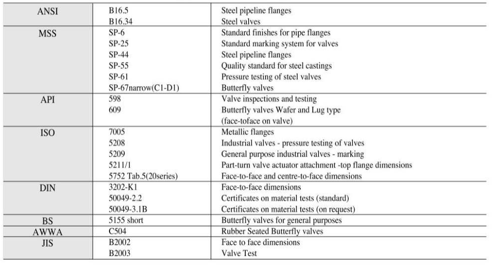
Inspection and testing in according to 1505205, MSS SP61, AWWA C504, JIS 82003, API 598, and 855155
The body test is performed (It 1.5 times the nominal pressure while the Seat Test at 1.1 times the nominal pressure, using for both emulsified water ar room temperature. While testing, no leakage sball be noticed from the stems. as for the Body Test, not from upstream to downstream, as for the Seat TeSL For the Pneumatic Test with disc closed the butterfly is covered with water and soap on that side where the visual control if the seal is performed. in order to show up a possible leak. Our valves are tested 100% before being delivered.
Pressure / Temperature Ratings
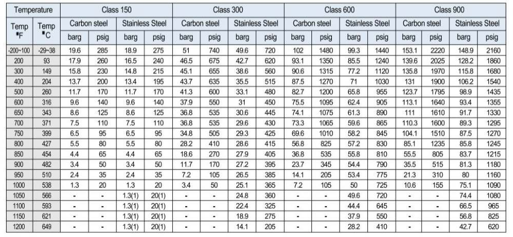
- WCB permissible but not recommended for prolonged u e above 426-C (SOO·F)
- for welding end valves only. flanged end rating terminates at 53S-C (IOOO·F)